
Every fixing. Every door type.
43 fixing options across 8 methods — for timber, metal and glass doors. Diagrams, technical specs, and product codes.


What this page is
A working fixings reference for specifiers, architects and installers. Every fixing kit Ash supplies with a pull handle is catalogued here — from the F1 back-to-back spindle for timber doors to the F21.110 single-sided bolt for thick glass-clad metal assemblies.
The diagrams and product codes match those embedded in our handle spec sheets, our quotation paperwork, and the labels on the parts you'll receive in the box.
How to use it
1. Find your door type in the material grid below.
2. Pick the F-code that matches your door thickness.
3. Read the install method that fixing belongs to.
4. Request a fixings sample kit and we'll ship the exact pieces for your project to test before commitment.
Choose by door material
Timber doors
Solid timber, engineered timber and veneered cores. Back-to-back spindle or face-fix rose disc both work cleanly.
See methods 1, 2, 3, 5, 6, 8Metal doors
Steel, aluminium and PPC-coated frames. F11 block with M6 rivnut is the standard hidden face fix; F4 covers glazing-rebate retrofits.
See methods 1, 2, 3, 4, 5Glass doors
Toughened glass 10–25mm. All fixings ship with nylon washers and protective sleeves to prevent point loading.
See methods 1, 3, 6, 7Fire doors
FD30 and FD60 cores. Through-fixings preserve the rated assembly — specify Methods 1, 2 or 6 and confirm against the door manufacturer's certification.
See fire-door guidanceThe 8 fixing methods
Bolt-Through Back-to-Back Pairs with Grub Screw
F16 · F18 · F20
The mechanically strongest fixing in the catalogue. Default specification for high-traffic public doors that take handles on both sides — a threaded spindle ties the two handles together and the grub screw engages a machined slope to pull the interior handle flush.
- Thread the Spindle (Exterior Handle): Screw the threaded fixing spindle directly into the designated fixing points on the exterior handle. Glass Doors: slide nylon washers over the spindles now.
- Insert Through Door (Alignment): Push the threaded spindles cleanly through the pre-drilled holes in the door face.
- Align the Slopes (Interior Handle): Offer up the interior handle. Line up its internal grub screw holes so they match the machined slope on the fixing spindle.
- Lock the Grub Screw (Final Fastening): Place the interior handle over the spindles. Use a 3mm Allen key to tighten the M6 grub screw firmly.
Note: When the grub screw engages the slope correctly, it mechanically pulls the handle tight and flush against the door face.


Single-Sided Bolt-Through Countersunk Machine Screw
Used where the door takes a handle on one side only and a clean countersunk machine screw can be presented from the back. Fast to install on timber and metal doors that can be drilled through cleanly. Pairs naturally with our push plates on the reverse face.
- Insert Screws: Push the countersunk machine screws through the holes from the opposite side of the door.
- Hand Thread: Align the handle on the door face and turn the screws by hand into the handle's threaded fixing points to avoid cross-threading.
- Tighten Home: Use an Allen key or screwdriver to tighten down the countersunk screws until the handle is firmly secured.


Single-Sided Bolt-Through with Decorative Cap
F9A · F10A · F19 · F21

The standard fixing for glass shopfront and retail doors taking a single-sided pull. A decorative cap on the back of the door conceals the bolt and presents a clean reverse face — available in finishes that match the handle. Glass installations always ship with nylon washers.
- Align & Insert: Push the fixing bolt through the door from the back and line it up with the fixing points on the handle.
- Glass Doors: Place a nylon washer between the handle/fixing block and the glass door face.
- Tension: Insert a 3mm Allen key into the tension hole of the decorative cap assembly and tighten the bolt thoroughly for a completely rigid connection.


Single-Sided Hidden Fix in Rebate

These handles must be fully installed prior to the glazing of the doors. Once the rebate is closed up by the frame, access to the fixing is no longer possible.
Used on framed glass doors and concealed-panic-bar aluminium styles where no fixing must be visible from either face. The bolt is concealed inside the glazing rebate and accessed during construction. A portion of the glazing rebate area is removed prior to installation.
- Access Drill Path: Create an access hole in the side of the glazing rebate to push the machine bolt through and align it with your hole centres.
- Secure Fix: Insert the bolt through the rebate hole into the handle's fixing point. Use a 13mm or 17mm spanner to tighten the fixing securely.

Single-Sided Hidden Face Fix — F11 Block System
Our hidden face fix for installations where the back of the door must read completely clean. The F11 block is fastened to the door face first; the handle then slides over the blocks and locks down via grub screws. Substrate determines whether the block is secured with a rivnut (metal) or wood screw (timber).
- Drill Centres: Drill a 9mm hole at the designated fixing centres on the door face.
- Install Rivnut: Insert the M6 rivnut into the drilled hole and compress firmly using a rivnut tool.
- Mount Block: Use the M6 machine screw to fasten the F11 fixing block securely.
- Secure Handle: Place the handle over the mounted F11 blocks. Use a 3mm Allen key to tighten the grub screws — the handle draws itself tightly against the door face.
- Mount Block: Use a heavy-duty timber wood screw to fasten the F11 fixing blocks directly to the door face.
- Secure Handle: Slide the handle over the F11 blocks and use a 3mm Allen key to tighten the grub screws until the handle pulls flush.
Back-to-Back Bolt-Through with Dome Nuts
An alternative back-to-back fix where the dome nut becomes part of the decorative reveal. Specified on hospitality and retail fit-outs where a softer aesthetic is wanted on the reverse face. F7 is the glass-door variant with protective pads and sleeves.
- Insert Spindle: Push the threaded spindle through the pre-drilled holes in the door.
- Position Handles: Place handles over the protruding threaded spindle on both sides.
- Glass Doors: Glazing pads between hardware and glass.
- Tighten Dome Nuts: Thread dome nuts onto spindle ends and crank evenly with a 13mm spanner.
Single-Sided Bolt-Through with Dome Nuts

Single-sided variant for doors with a handle on one face only. The threaded spindle includes an integrated decorative bolt on the back; the handle locks onto the front via dome nuts. F7A is the glass-door variant supplied with protective pad and sleeve.
- Insert Assembly: Feed the threaded spindle (with integrated decorative cap) through the holes from the back of the door.
- Offer Handle: Position the single-sided handle over the protruding spindle on the face.
- Lock Down: Use a 13mm spanner to tighten the dome nuts down securely.
Single-Sided Rose Disc Fix
Surface-fix to timber or aluminium doors where the back face is inaccessible or must not be drilled. Inner and outer cover rose conceals the fixing disc. Designed for 19mm and 25mm diameter pull handles only. Not recommended on fire-rated leaves without checking the door manufacturer's certification.
- Component Prep: Slide the decorative cover cap loosely over the handle neck first.
- Assemble Disc: Use the M8 countersunk bolt to screw the fixing disc securely to the base of the handle.
- Mount to Door: Position the assembly and use timber screws to fasten directly to the door face.
- Conceal Fixings: Push the decorative cover cap down firmly over the fixing disc to cleanly hide all screws.
F-code index — complete reference
| F-code | Door thickness | Fixing method | Substrate | Hole prep |
|---|---|---|---|---|
| F1.85 | 35–54mm | Method 1 · Back-to-back M12 spindle + grub screw | Timber / Metal | 12.5mm |
| F1.100 | 55–69mm | Method 1 · Back-to-back M12 spindle + grub screw | Timber / Metal | 12.5mm |
| F1.120 | 70–85mm | Method 1 · Back-to-back M12 spindle + grub screw | Timber / Metal | 12.5mm |
| F1.140 | 86–105mm | Method 1 · Back-to-back M12 spindle + grub screw | Timber / Metal | 12.5mm |
| F2 | 10–25mm | Method 1 · Back-to-back, washers + sleeves | Glass | 18mm |
| F2A | 10–25mm | Method 3 · Single-sided, decorative smooth-headed bolt | Glass | 18mm |
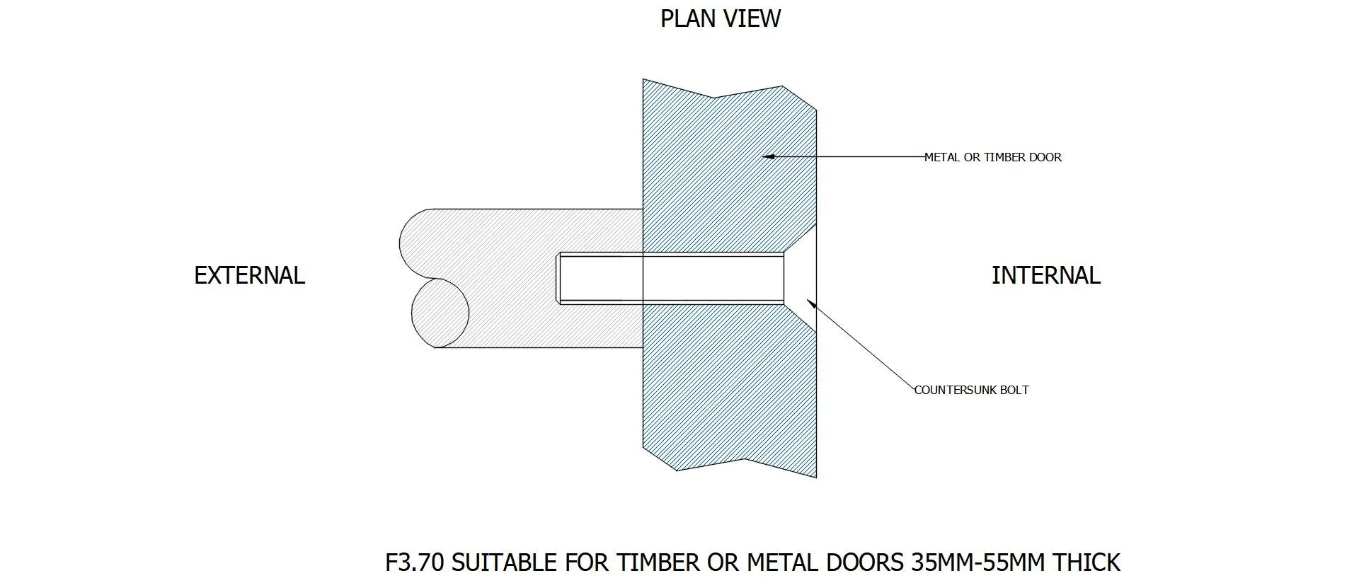
| F3.70 | 35–55mm | Method 2 · Countersunk M12 machine screw | Timber / Metal | 12.5mm CSK |
| F3.90 | 56–75mm | Method 2 · Countersunk M12 machine screw | Timber / Metal | 12.5mm CSK |
| F3.110 | 76–95mm | Method 2 · Countersunk M12 machine screw | Timber / Metal | 12.5mm CSK |
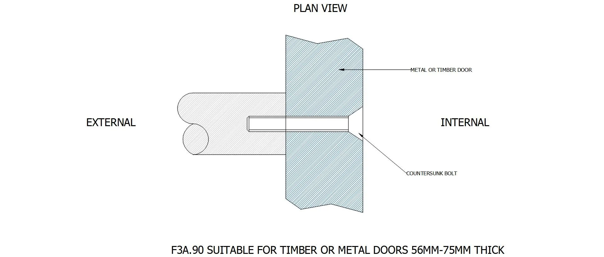
| F3A.70 | 35–55mm | Method 2 · Countersunk M8 machine screw | Timber / Metal | 8.5mm CSK |
| F3A.90 | 56–75mm | Method 2 · Countersunk M8 machine screw | Timber / Metal | 8.5mm CSK |
| F3A.110 | 76–95mm | Method 2 · Countersunk M8 machine screw | Timber / Metal | 8.5mm CSK |
| F4 | Glazing rebate | Method 4 · Hidden fix in rebate, M12 bolt + washer | 12.5mm | |
| F4A | Glazing rebate | Method 4 · Hidden fix in rebate, M8 bolt + washer | 8.5mm | |
| F5.70 | 35–55mm | Method 3 · Single-sided smooth-headed bolt (M12) | Timber / Metal | 12.5mm |
| F5.90 | 56–75mm | Method 3 · Single-sided smooth-headed bolt (M12) | Timber / Metal | 12.5mm |
| F5.110 | 76–95mm | Method 3 · Single-sided smooth-headed bolt (M12) | Timber / Metal | 12.5mm |
| F6 | Specify at order | Method 6 · Back-to-back threaded stud + dome nuts | Timber / Metal | 8.5mm |
| F6A | Specify at order | M3/M7 · Single-sided stud + dome nut + smooth bolt | Timber / Metal | 8.5mm |
| F7 | 10–25mm | Method 6 · Back-to-back stud + dome nuts, pads/sleeves | Glass | 12mm |
| F7A | 10–25mm | M3/M7 · Single-sided stud + dome nut, pads/sleeves | Glass | 12mm |
| F8 | 19/25mm pulls only | Method 8 · Face-fix rose disc with cover cap | Timber / Metal | Surface screw |
| F9.85 | 35–54mm | Method 1 · Back-to-back M8 spindle + grub screw | Timber / Metal | 8.5mm |
| F9.100 | 55–69mm | Method 1 · Back-to-back M8 spindle + grub screw | Timber / Metal | 8.5mm |
| F9.120 | 70–85mm | Method 1 · Back-to-back M8 spindle + grub screw | Timber / Metal | 8.5mm |
| F9.140 | 86–105mm | Method 1 · Back-to-back M8 spindle + grub screw | Timber / Metal | 8.5mm |
| F9A.70 | 35–55mm | Method 3 · Single-sided M8 smooth-headed bolt | Timber / Metal | 8.5mm |
| F9A.90 | 56–75mm | Method 3 · Single-sided M8 smooth-headed bolt | Timber / Metal | 8.5mm |
| F9A.110 | 76–95mm | Method 3 · Single-sided M8 smooth-headed bolt | Timber / Metal | 8.5mm |
| F10 | 10–25mm | Method 1 · Back-to-back M8 spindle, washers/sleeves | Glass | 12mm |
| F10A | 10–25mm | Method 3 · Single-sided smooth-headed bolt, washers/sleeves | Glass | 12mm |
| F11 | n/a (face fix) | Method 5 · Hidden face fix block + rivnut/CSK screw | Timber / Metal | 9.5mm |
| F11A | n/a (face fix) | Method 5 · Hidden face fix block variant + rivnut/CSK | Timber / Metal | 9.5mm |
| F16 | 10–25mm | Method 1 · Back-to-back M12, 19mm T-bar only | Glass | 18mm |
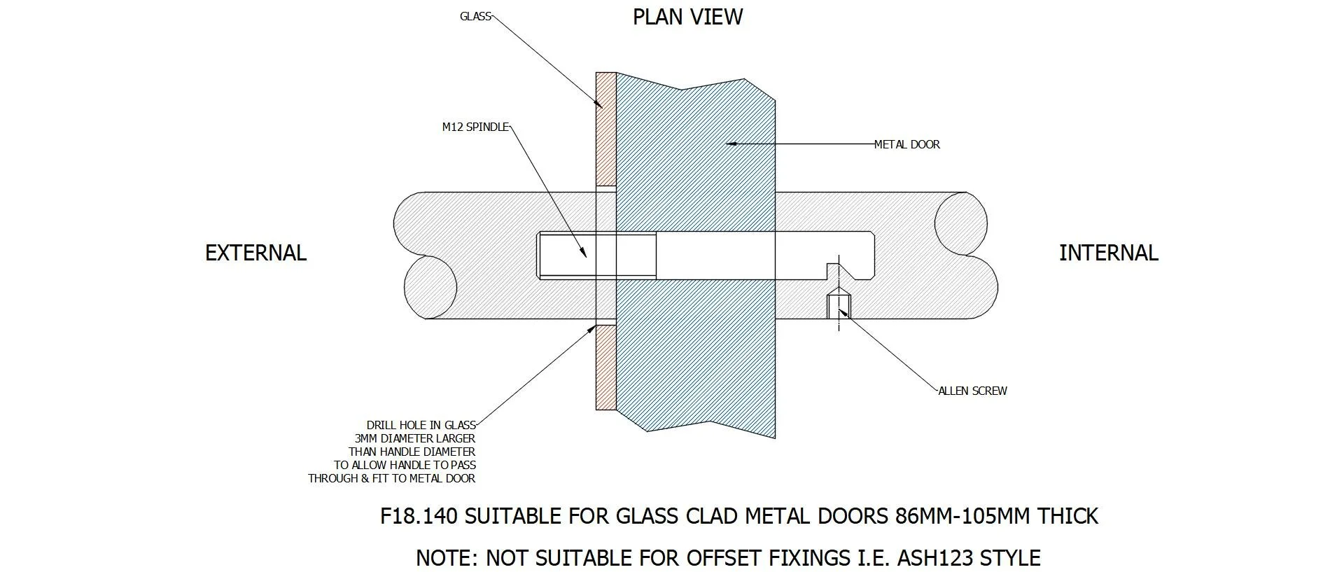
| F18.100 | 55–69mm | Method 1 · Back-to-back M12 spindle, glass-clad | Glass-clad metal | 12.5 / 18mm |
| F18.120 | 70–85mm | Method 1 · Back-to-back M12 spindle, glass-clad | Glass-clad metal | 12.5 / 18mm |
| F18.140 | 86–105mm | Method 1 · Back-to-back M12 spindle, glass-clad | Glass-clad metal | 12.5 / 18mm |
| F19.70 | 35–55mm | Method 3 · Single-sided M12 smooth-headed bolt | Glass-clad metal | 12.5 / 18mm |
| F19.90 | 56–75mm | Method 3 · Single-sided M12 smooth-headed bolt | Glass-clad metal | 12.5 / 18mm |
| F19.110 | 76–95mm | Method 3 · Single-sided M12 smooth-headed bolt | Glass-clad metal | 12.5 / 18mm |
| F20.100 | 55–69mm | Method 1 · Back-to-back M8 spindle, glass-clad | Glass-clad metal | 8.5 / 12.5mm |
| F20.120 | 70–85mm | Method 1 · Back-to-back M8 spindle, glass-clad | Glass-clad metal | 8.5 / 12.5mm |
| F20.140 | 86–105mm | Method 1 · Back-to-back M8 spindle, glass-clad | Glass-clad metal | 8.5 / 12.5mm |
| F21.70 | 35–55mm | Method 3 · Single-sided M8 smooth-headed bolt | Glass-clad metal | 12.5 / 18mm |
| F21.90 | 56–75mm | Method 3 · Single-sided M8 smooth-headed bolt | Glass-clad metal | 12.5 / 18mm |
| F21.110 | 76–95mm | Method 3 · Single-sided M8 smooth-headed bolt | Glass-clad metal | 12.5 / 18mm (+2mm in glass) |
Specifier FAQ
Q.01
Which fixing for a glass shopfront door?
+
For a single-sided pull on a toughened glass shopfront door (10–25mm), specify F2A or F10A — Method 3 single-sided bolt-through with a decorative smooth-headed cap. For back-to-back pulls, specify F2 (M12) or F10 (M8) under Method 1. Both ship with nylon washers and protective sleeves to prevent point loading. For 19mm T-bar handles on glass, specify F16.
Q.02
Are Ash fixings suitable for fire doors?
+
Yes — through-fixings preserve the rated integrity of the door assembly. Specify Methods 1, 2 or 6 (F1, F3, F3A, F6, F9) for FD30 and FD60 cores. Avoid the F8 rose disc surface-fix on rated leaves without explicit confirmation from the door manufacturer's certification. Send us your door schedule with the fire strategy and we'll confirm the correct fixing before manufacture.
Q.03
Do you supply glazing pads with glass-door handle fixings?
+
Yes. Nylon washers, plastic ferrules and glazing pads are supplied as standard with every fixing kit destined for a glass-door installation — F2, F2A, F7, F7A, F10, F10A, F16. They sit between every metal component and the glass face to absorb load and prevent the bolt or fixing block from making point contact with the glass. If your project drawings flag glass substrate, the correct pads are already in the box.
Q.04
Can I order a fixings sample kit?
+
Yes — we routinely ship sample fixings to specifiers and contractors for installation trials before commitment. Send us the F-codes you want to test (or the door schedule and we'll select for you) via the contact page. Sample kits typically include the spindle/bolt, washers, sleeves, decorative caps and Allen key required to dry-fit on a test panel.
Q.05
What's the difference between F2 and F2A?
+
Both are M12 fixings for 10–25mm toughened glass doors and both ship with the same washer and sleeve set to protect the glass. F2 is back-to-back — two handles connected by a threaded spindle with the interior handle locked via a grub screw (Method 1). F2A is single-sided — one handle on the face, fixed with a decorative smooth-headed bolt that finishes the reverse cleanly (Method 3). Choose F2 when handles are needed both sides; F2A when the back of the door takes a push plate, panic bar or no hardware at all.
Send your door schedule. We'll confirm the F-code.
Door thickness, substrate, fire strategy, handle profile — we'll spec the correct Ash fixing method against your project and ship a sample kit before commitment.
Request a Fixings Specification